


Sidel SBO 10 Still Water Bottle Blow Moulder


Sidel SBO 10 Still Water Bottle Blow Moulder
Description
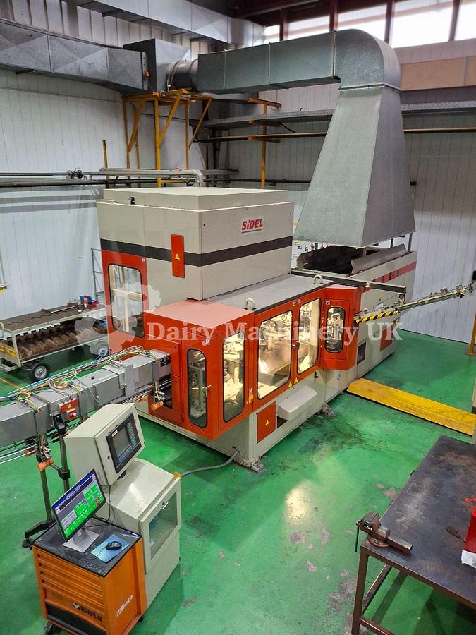
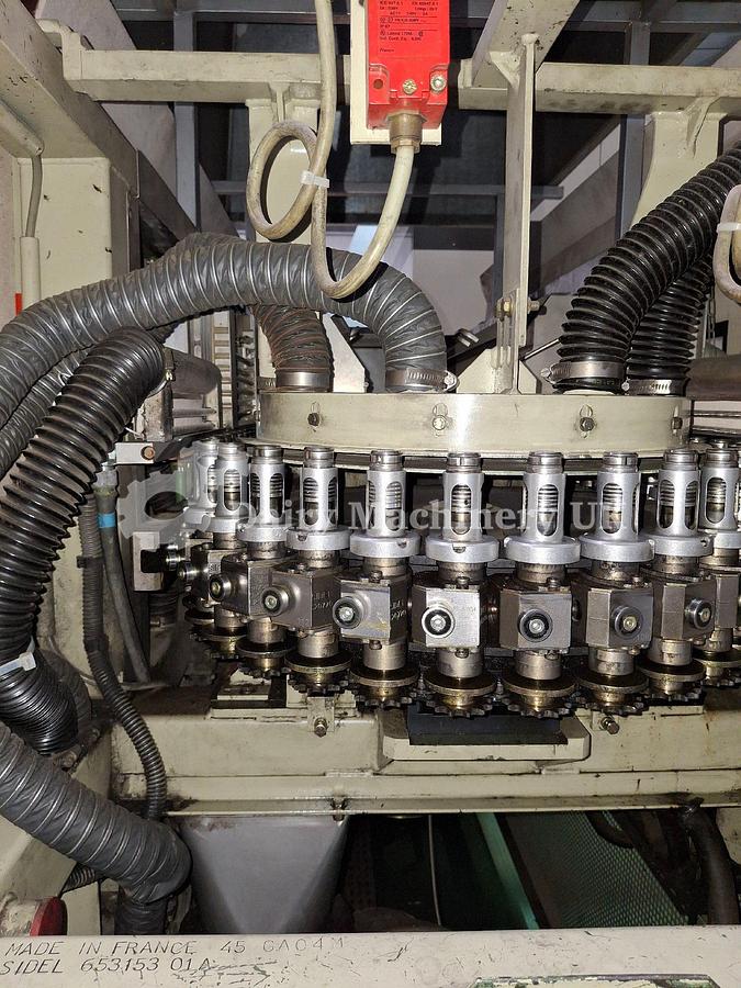
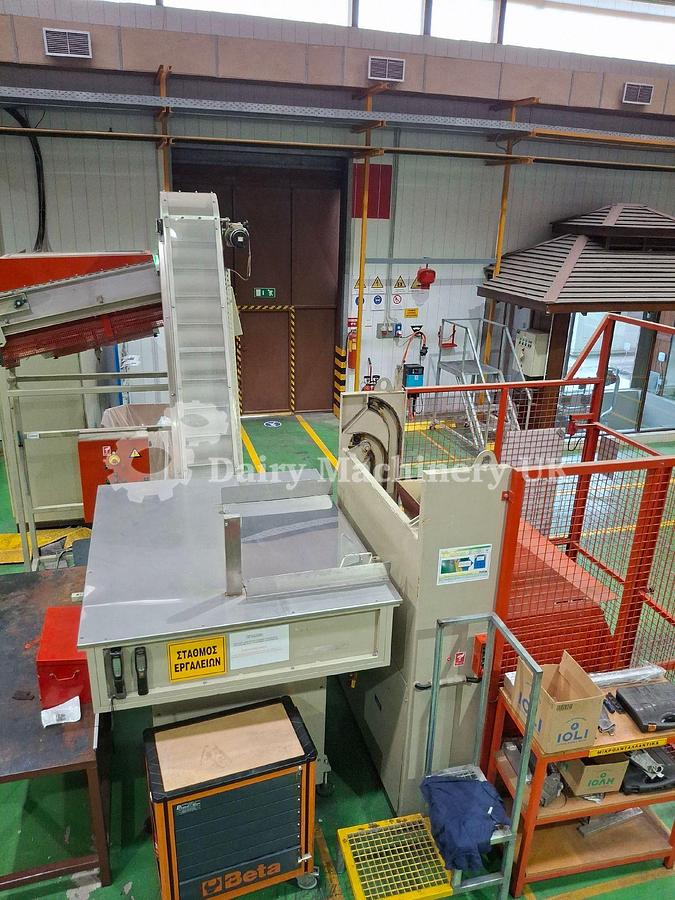
SIDEL SBO10- blowing machine
SBO10 is intended to manufacture PET bottles. Its production rate can be up to 10.000 bottles per hourdepending on the capacity.
As first step, the operator puts the preform bin, via trans pallet or forklift, in the hoisting and tipping unit (SAMETO brand) and the preforms inserts in the hopper.
After that, the elevator transfers the preforms to the horizontal elevator, the unscrambler and the final gravity guide (infeed rails).The below schematic diagram describes the general process of SBO10 machine:
which consists of:
1. Preform infeed rails
2. Preform infeed wheel
3. Infrared oven
4. Preform transfer wheel
5. Blow wheel
6. Bottle transfer wheel
7. Bottle evacuation
GENERAL Presentation
1. Infeed of cold preforms
Cold preforms are inserted by an inclined ramp. They are hung by the neck and are guided by two rails between which they are lowered by gravity.
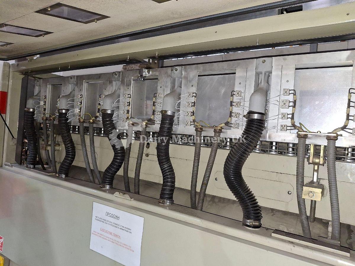
2. Preform heating linear oven
The preforms, grasped in the spindles at the neck, are turned 180 degrees so that they are head down and are made to rotate as they pass in front of infrared lamps. The linear oven has 10 heating modules. Each oven module has 8 infrared lamps. Ath oven exit, an infrared camera reads the preform temperature so as the automatic regulation of all the areas coming under its control.
3. Hot preform transfer wheel
A transfer wheel with 6 arms conveys the hot preforms through the blowing moulds when they leave the oven.
4. Preform ejection
An ejection system is mounted after the preform transfer wheel, in case of a non correct temperature of a preform.
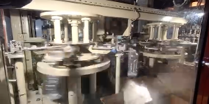
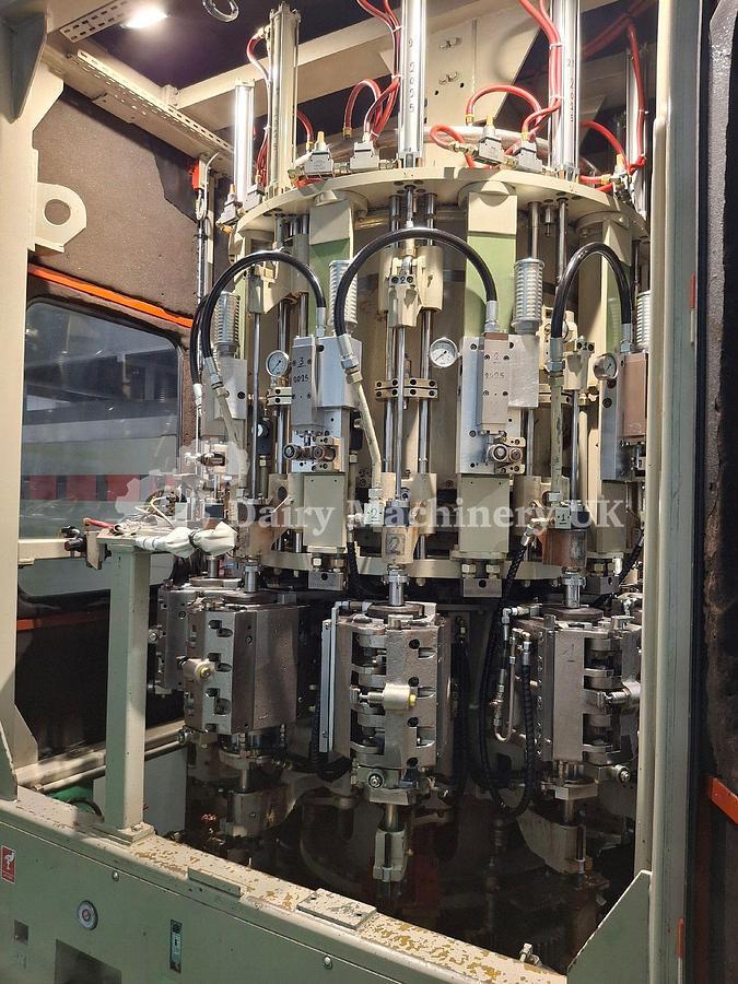
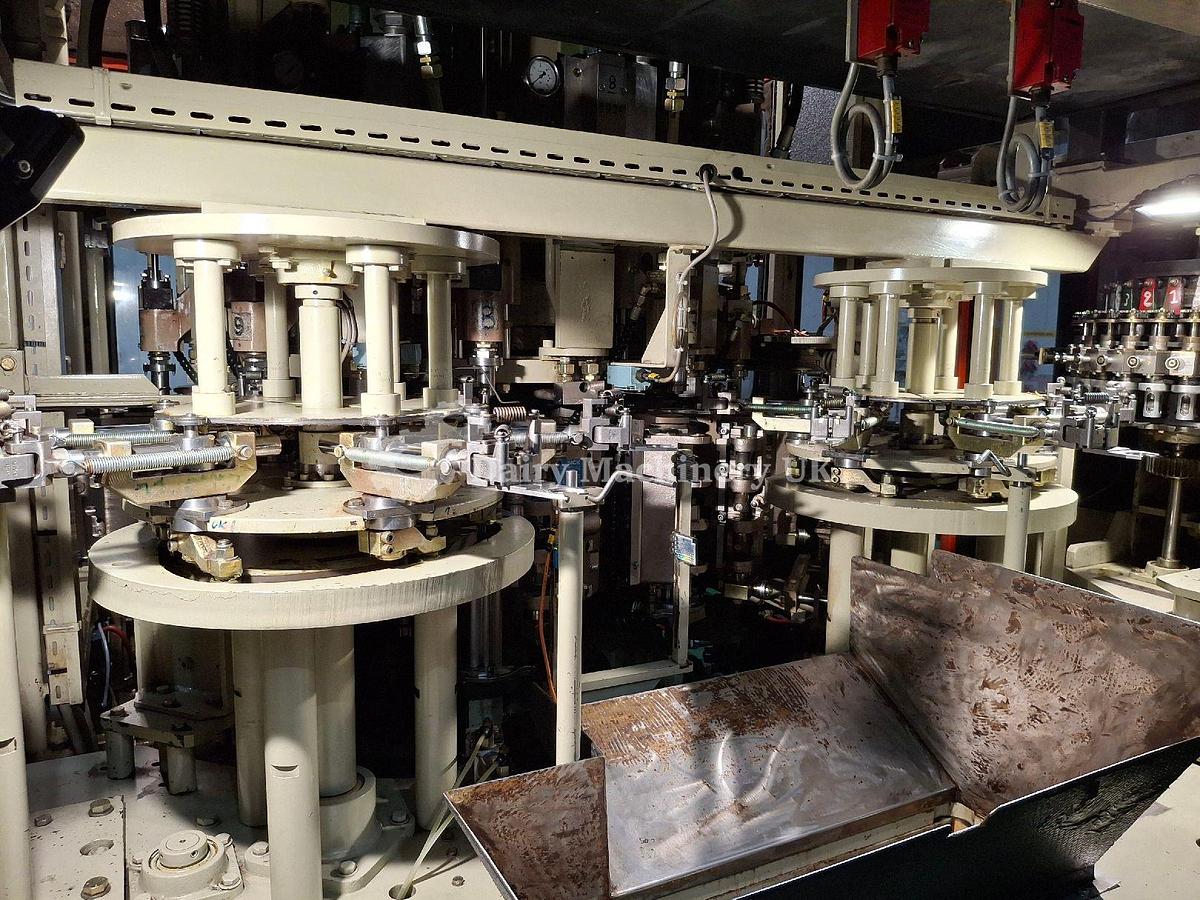
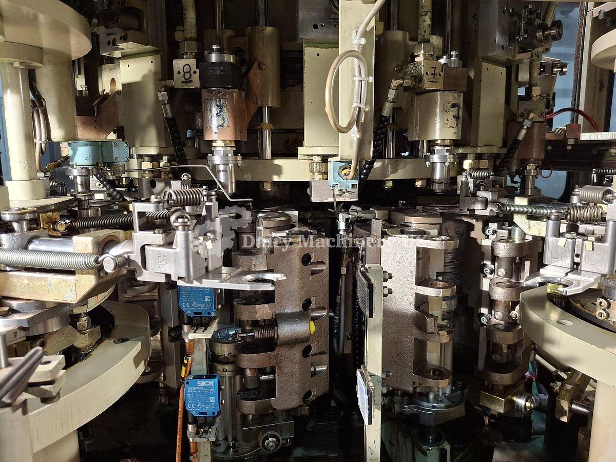
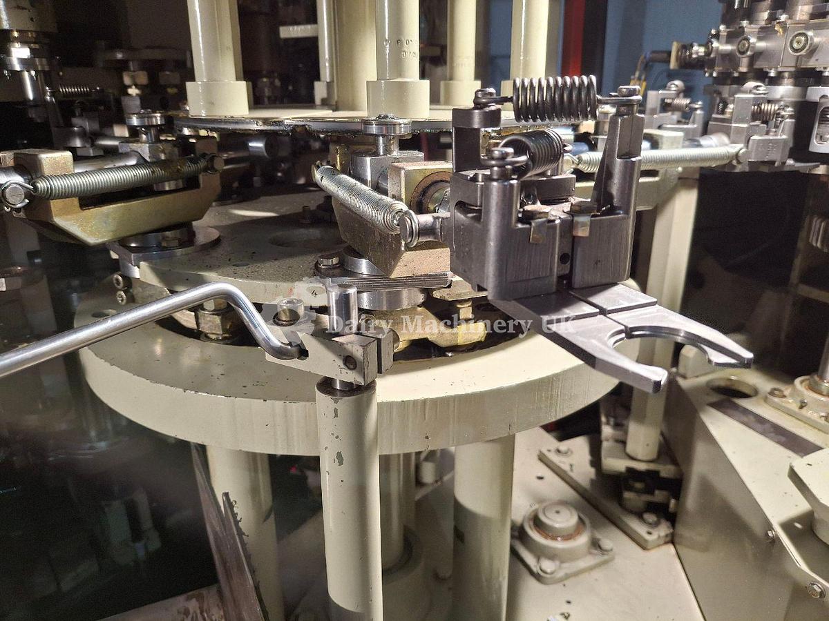
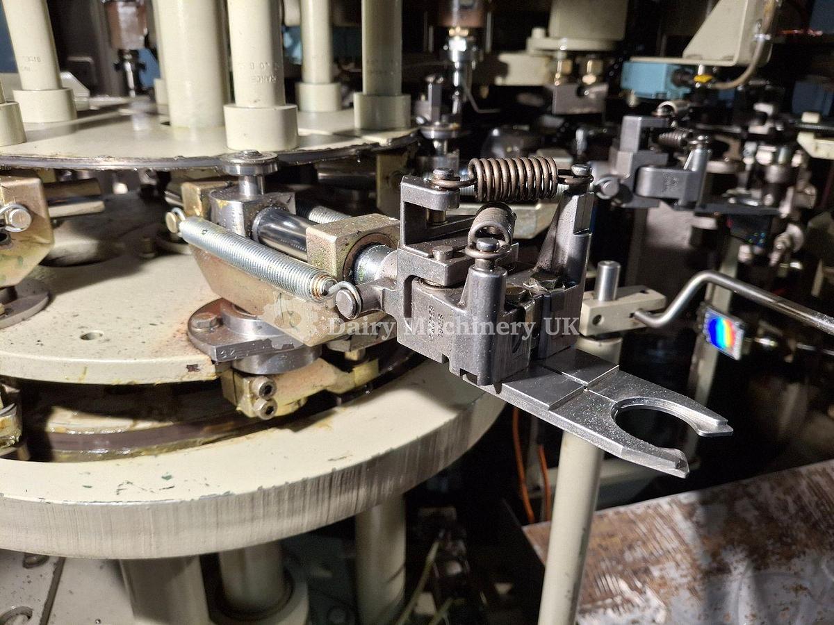
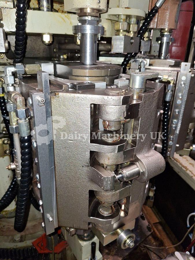
5. Blow wheel
Preforms are put in the mould for which opening and closing are assured by a system of connecting rods operated by a cam. The mould is locked by a mechanical device. Blow nozzle guides the stretching rod, which ensures longitudinal orientation. A set of cameras synchronizes the whole process. The moulds are controlled for temperature by chilled water circulation.
6. Bottle transfer wheel
A transfer wheel with 6 arms picks up the bottles in the moulds to evacuate them from the blowing wheel.
7. Bottle ejection
An ejection system is mounted after the bottle transfer wheel. It is completed by a set of photocells. If the bottle is not correct, it is ejected.
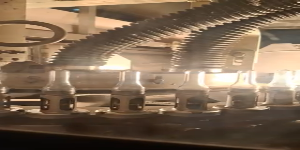
8. Bottle outfeed wheel.
An outfeed wheel with 8 notches receives the bottles comes from the transfer arms and puts them down on a belt. They are held by guides. The bottle outfeed can be linked to a conveyor system.
- Hoisting and tipping unit (1996)
- Hopper (1995)
- Elevator (1995)
- Orienting rollers (1995)
- Unscrambler (1995)
- Gravity rails (1995)
- linear oven (1995)
- Blow wheel with 10 moulds (1995)
- Bottle outfeed wheel (1995)
- Operator control panel (1995)
- Electrical cabinets (1995)
12. Chiller (1998)
Energy and fluid consumption
1.
Electricity
Max supplied power: 216kW
Average consumption: 120 to 160 kW/h according to item
Voltage: 380 (3phase)
Frequency: 50/60 Hz
2.
Compressed air
Supplied power: from 7 to 35 bar
Control air
pressure: 7 bar
flow: 60 to 125 Nm3/h according to item
Air quality: dry air, deoiled and filtered to 0,1 ppm
Spherical base pressure: up to 25bar
flow: 170 to 830 Nm3/h
Free standing base
pressure: up to 35 bars
flow: 235 to 1.100 Nm3/h
3.
Chilled water
temperature: 10 to 12 celsium degrees
pressure: 5 to 6 bars
flow: up to 9 m3/h
calories to be removed: up to 22.000 Kcal/hour
Specifications
| Model | SBO 10 |
| Year | 1995 |
| Condition | Used |
| Stock Number | 827 |
| Max supplied power | 216kW |
| Voltage | 380 (3phase) |
| Frequency | 50/60 Hz |
| Pressure | 7 bar |
| Spherical base pressure | up to 25bar |
| Flow 2. | 170 to 830 Nm3/h |
| Pressure 1. | up to 35 bars |
| Flow 1. | 235 to 1.100 Nm3/h |
| Pressure 2. | 5 to 6 bars |
| Cap Size | 29/25 |
| Flow | up to 9 m3/h |
| Calories to be removed | up to 22.000 Kcal/hour |
| Condition | Good still on operation |
| Available | End of 2025 |